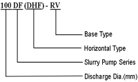
Vertical pumps foam series DF (DHF) or foam centrifugal pumps are designed for double skin design, including pump foam rubber backing, centrifugal pump, foam pump for mining. These vertical pumps foam is characterized by high efficiency, wear resistant, stable performance and high interchangeability. The lining material and the impeller is of wear-resistant rubber or metal. The pump does not need vertical foam seal, and bin liner can be used. Vertical froth pumps may transporter more mud flow and high head with small installation space. Vertciales foam pumps can be driven by belt or direct coupling. Centrifugal pumps foam DF series (DHF) must rotate in the direction of clockwise from the driving end.
Application
Foam centrifugal pumps can be used for industrial flotation, ideal for transporting foam lodo.
Characteristics of Vertical Froth Pumps
Foam pumps are suitable for conveying the foam slurry, especially by flotation processes. You can remove the foam mud and function normally even if the support is not enough mud. The wetted parts of the pump are made of Ni-hard alloy materials and very wear resistant chromium. The discharge chute is a steel structure. It may be coated with different materials. The direction of the discharge pump can be oriented in a range of 45 °. This series of pumps with rubber foam adopt a dual coating structure with stable performance, high efficiency, high wear resistance and interchangeability of components. Propellant material and coating are resistant metal or rubber desgaste.
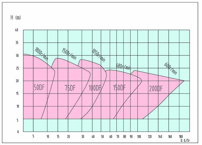
Selection BoxPatameter performativeSettings
| Kind | Capacity (Q) | Head (H) | Speed (n) | Maximum Efficiency | Max size. Permitted particle | Max. Permitted Union |
| (M³ / h) | (L / s) | (M) | (R / min) | (%) | (Mm) | (KW) |
| 50DF | 4.3 ~ 51 | 1.2 ~ 14.2 | 6.2 ~ 30.2 | 800 ~ 1800 | 20 ~ 45 | 35 | fifteen |
| 75DF | 10.8 ~ 149.4 | 3 ~ 41.5 | 6.5 ~ 29.5 | 700 ~ 1500 | 20 ~ 55 | 38 | 20 |
| 100DF | 10.8 ~ 212 | 3 ~ 59 | 6.8 ~ 29.2 | 500 ~ 1050 | 20 ~ 55 | 55 | 40 |
| 150DF | 36 ~ 425 | 10 ~ 118 | 6.8 ~ 25.2 | 350 ~ 680 | 20 ~ 55 | 63 | 75 |
| 200DF | 230 ~ 670 | 64 ~ 186 | 5 ~ 24.8 | 350 ~ 680 | 20 ~ 55 | 72 | 75 |
Installation dimension.png)
.png)
| Kind | Outline Dimensions | | H | H1 | H2 | H3 | H4 | H5 | L | L1 | L2 | L3 | L4 | φD | N | P | | 50DF | 382 | 1140 | 850 | 1300 | 12 | 474 | 138 | 360 | 210 | 480 | 380 | 938 | 174 | 110 | | 75DF | 467 | 1250 | 950 | 1400 | 12 | 474 | 149 | 354 | 262 | 510 | 445 | 938 | 174 | 110 | | 100DF | 506 | 1720 | 1310 | 1910 | 16 | 637 | 229 | 537 | 338 | 740 | 6 o'clock | 1444 | 238 | 170 | | 150 DF | 791 | 2430 | 1950 | 2770 | 20 | 875 | 318 | 696 | 460 | 1020 | 800 | 1970 | 300 | 210 | | 200 DF | 791 | 2430 | 1950 | 2770 | 20 | 875 | 381 | 696 | 470 | 1020 | 800 | 1970 | 300 | 210 |
|
| Kind | Dimension of inner flange | Flange External Dimension | | D1 | D ' | Φ1 | n1 | Φd1 | δ1 | D2 | D ' | Φ2 | n2 | Φd2 | δ2 | | 50DF | 51 | 146 | 184 | 4 | 19 | 25 | 102 | 178 | 216 | 4 | 19 | 12 | | 75DF | 76 | 191 | 229 | 4 | 22 | 27 | 152 | 235 | 279 | 8 | 18 | 16 | | 100DF | 102 | 235 | 279 | 4 | 22 | 32 | 203 | 292 | 337 | 8 | 19 | 12 | | 150DF | 152 | 324 | 365 | 8 | 21 | 38 | 305 | 406 | 457 | 12 | 22 | 20 | | 200DF | 203 | 375 | 432 | 8 | 29 | 44 | 305 | 406 | 457 | 12 | 22 | 20 |
|


.png)
.png)

